
Vision Placer V3 Software preview
We are developing a new PC software on Windows and Linux to operate pick & place machines.
Here is a short preview of our new parametric driven vision system and pnp editor.
All pictures shown are still from our beta software and not the final version and precision.
The gerber import help to do the offline programming and checks by using cross probing and multiple selection tools. Inside the job control tab you are able to simulate PNP strategy using PC and machine.
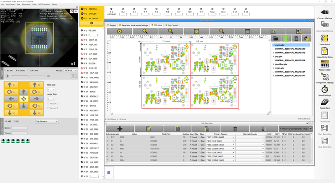
Our project editor support panelizing setup and a pair of marks for each PCB inside of a panel.
We support a machine driver DLL containing machine controller specific adoption code so it is possible to control nearly every pick and place machine using PC vision and motion / machine controller.
The machine control DLL SDK will be available as source code framework to add custom machines by yourself.

Video window docked out for dual screen setup

Project settings

The video window can be docked out to a separate monitor if dual screen is available.
All Informations about the pnp job are collected inside the first tab.
PCB preview and data cross probing

Cross probing between PNP data grid and PCB preview is possible by selecting part or row.
Multiple selection in data grid will highlight all selected parts.
Layer management
We can add gerber layers and PNP data to our preview.
In place editors

Panel setup

Define row and column count plus spacing and the system will arrange the PNP data for panel placement.
You can add a pair of mark points (fiducials) to each PCB on the panel.
Panel selection for placement


Any PCB can be switched on and off for placement to skip broken PCB inside a panel.
Edit bottom side in the same project file


Assign mark points (fiducials) settings by selecting gerber primitives

Multi selection to highlight all component positions in PCB overview.

Selective parts display

Unmounted parts view

Mount parts view

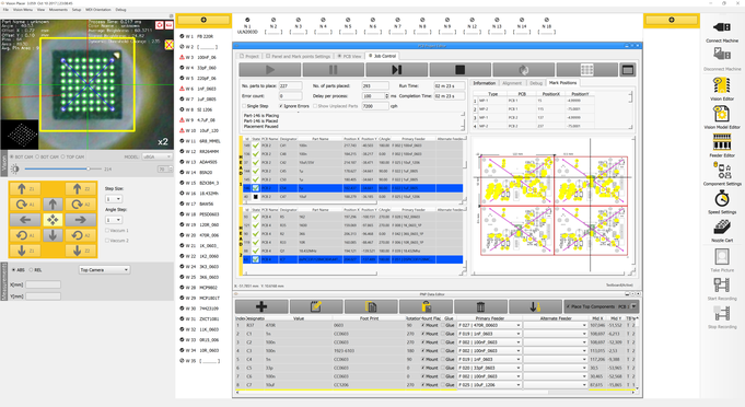
Job Control Panel
After alignment all parts where added to the PNP list. Current part will be marked in PCB overview.
All placed parts will be flagged and marked yellow. Skipped parts because of feeder error can be placed again at the end of the job. The system changes unplaced parts in a temporary file and on next project load it will ask to reload the last placement state.

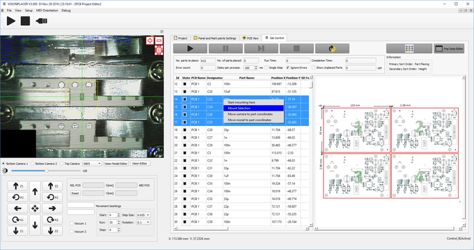
Placement strategy settings

Placing selected parts or start placement from a selected position.
Feeder stock editor

Component database

Speed editor

Vision Model settings

This is the vision editor.
You assign a vision model to any feeder line.
This model can be user defined inheriting base model attributes.
The Visual area can be defined and the threshold setting adjust the image conversion to B/W.
A bend pin detector can be enabled the results shown below.
The area detector is used to detect if the part was taken up in the right direction or if a different part hangs under the nozzle than expected.
Every model can use different compensation and precision settings for the visual alignment.
Bend pin detection


The video output can be zoomed and zooming will be stored inside the model


Some detection examples SSOP-16, TQFP-44, MLF-24, SOT23-5, SOT-89


Pin one detection examples showing box and pin alignment function


SOT23-5 PIN one detection after pickup and applied alignment

After pick up!

Alignment and pin one detection applied!
Loose part detection function

Loose part detection use models searching for similar color and same area parts. The pnp machine recive a list of part center and object count for pick up.

If there are other parts inside the pocket the machine will ignore this if size and color don't match!
Mark detection


Mark detection has 3 base models for circle, square and cross.
You need o define the mark size and the mask opening.
Ambient light compensation

Ambient light -25%

Ambient light set point

Ambient light +25%
The ambient light level will be calculated and stored on model creation. Every threshold calculation based on this set point. If ambient light changes the system compensate the threshold.
Here are the example pictures for reference


